

We provide the system engineering and integration support to a consortium including, among others, the Observatory of Geneva, EPFL and the Max Plank Institute for Astronomy.
PRIMA foresees the possibility of installing up to eight DDLs. However, for the operation with two telescopes only four are needed (1 per object and per telescope) and will be built in a first phase.
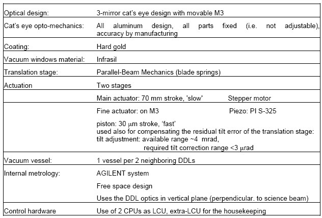
A schematic overview of the DDLs is presented in the next figure. The heart of the DDL is the retro-reflector, which has to retro-reflect the incoming beam in a perfectly parallel beam and displaced laterally by exactly 120 mm. Because of the requirements to re-image the pupil of each beam at a defined position a cats eye design has been chosen. The cats eye is composed of a 3-mirror telescope made of a parabolic collimator (M1), a hyperbolic secondary mirror (M2), and the curved tertiary (M3).
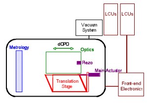
DDL schematics
The retro-reflector is fixed on a translation stage that allows to displace the retro-reflector along the optical axis in order to vary the dOPD.
Out of various design options we have chosen a fully mechanical blade-spring solution. This design ensures frictionless motion, high transversal rigidity, and accurate and reproducible guiding over the full mechanical stroke of 70 mm. The drawback of this choice is that one has to use a high-force actuator to overcome and hold the spring force, and, at the same time, to provide high positioning resolution.
The trade-off analysis between low power consumption, high resolution and high band-width led to the decision of separating the actuation in two stages:
- A high-precision stepper motor (however controlled in phases) acts directly on the translation stage and provides a coarse displacement of the whole cats eye over the full stroke.
- A second fine stage, a piezoelectric actuator, moves the M3 mirror of the cats eye, providing high bandwidth and resolution along three degrees of freedom: piston (the DDL main function) and tip/tilt (for correcting the repeatable flatness errors of the translation stage).
The dOPD introduced by the cats eye is measured with a resolution and repeatibility of better than 1 nm by means of a laser metrology system. The laser beam passes the DDL similarly to the scientific beam, but in perpendicular direction, i.e. the output pupil is placed above the input pupil. This layout has the advantage of not crossing the scientific beam, while still guaranteeing that the measured relative dOPD is the same as for the scientific beam. The commercial laser metrology system is robust and reliable. However, it provides only a relative position that needs to be reset to some reference position during the initialization process. This reference position is provided by an electrical micro-switch placed close to the end switches and provides an absolute accuracy of 1 um.
As mentioned previously, coarse and fine stroke actuation have been separated.
This solution has two advantages: first, it releases the requirements towards the mechanical accuracy of the coarse actuator. Second, it allows to applying the fast and precise correction by moving only a small mass, the M3 mirror. The coarse (main) actuator, which moves the whole optics mounted on the translation stage, consists of a high-accuracy stepper motor. The fine motion of the M3 mirror is provided by a high-resolution piezoelectric actuator.
Each DDL will be controlled by a separate Local Control Unit. One LCU will be used for housekeeping tasks, in addition to its DDL control task. Hardware, which needs to be close to the DDLs, is located in a special front-end electronic box. Excess heat will be evacuated via the cooling system of the interferometric laboratory.
The DDL Control Software (DDLCS) will be based on the same principle as for the main delay lines. It will allow to operating the DDLs in all the foreseen operation modes, while still keeping the number of SW functions limited and the interfaces with the VLTI SW simple. Because of the use of non-standard components, some special SW devices will have to be developed, in particular those for the motors. In addition, the OPD control loop of the DDLs has been designed and will be developed specially for the DDLs, and tailored to its peculiarities such as the two-stage actuation. The DDL OPD control software will run on the LCUs and will be coded in TAC.
A specialized LCU takes care of the environment, the temperature measurement inside the vessel, on the input window, on the table and in the electronics. The measurement of the pressure inside the vessel is also transmitted to this LCU. A parallel IO board monitors some states in the electronics, for example, the status of the power supply in the FEE and pumping stand.
DDL design baseline
